- 您现在的位置:买卖IC网 > Sheet目录1991 > CS4392-KZZ (Cirrus Logic Inc)IC DAC 24BIT 192KHZ W/VC 20TSSOP
CS4392
34
DS459PP3
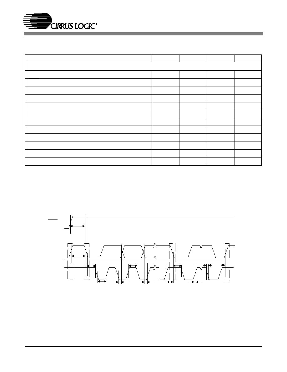
SWITCHING CHARACTERISTICS - CONTROL PORT INTERFACE
(Inputs: logic 0 = AGND, logic 1 = VL)
Notes: 6. Data must be held for sufficient time to bridge the 300 ns transition time of SCL.
Parameter
Symbol
Min
Max
Unit
I2C Mode
SCL Clock Frequency
fscl
-
100
kHz
RST Rising Edge to Start
tirs
500
-
ns
Bus Free Time Between Transmissions
tbuf
4.7
-
s
Start Condition Hold Time (prior to first clock pulse)
thdst
4.0
-
s
Clock Low time
tlow
4.7
-
s
Clock High Time
thigh
4.0
-
s
Setup Time for Repeated Start Condition
tsust
4.7
-
s
SDA Hold Time from SCL Falling
(Note 6)
thdd
0-
s
SDA Setup time to SCL Rising
tsud
250
-
ns
Rise Time of Both SDA and SCL Lines
tr
-1
s
Fall Time of Both SDA and SCL Lines
tf
-300
ns
Setup Time for Stop Condition
tsusp
4.7
-
s
t
buf
t
hdst
t
hdst
t
lo w
t r
t f
t
hdd
t
high
t sud
t sust
t susp
Stop
S ta rt
Sta rt
Stop
R e p eated
SDA
SC L
t
irs
RST
Figure 38. I2C Mode Control Port Timing
发布紧急采购,3分钟左右您将得到回复。
相关PDF资料
CS4397-KSZ
IC DAC 24BIT MULTY STNDRD 28SOIC
CS4398-CZZ
IC DAC 120DB 192KHZ W/VC 28TSSOP
CS43L22-CNZR
IC DAC W/HDPN & SPKR AMPS 40-QFN
CS4461-CZZR
IC ADC PSR FEEDBACK 24-TSSOP
CS5340-CZZ
IC ADC AUD 101DB 200KHZ 16-TSSOP
CS5340-DZZR
IC ADC AUD 101DB 200KHZ 16-TSSOP
CS5341-DZZ
IC ADC AUD 105DB 200KHZ 16-TSSOP
CS5342-CZZ
IC ADC AUD 105DB 200KHZ 16-TSSOP
相关代理商/技术参数
CS4392-KZZR
功能描述:数模转换器- DAC IC 114dB 192kHz Stereo DAC w/DSD RoHS:否 制造商:Texas Instruments 转换器数量:1 DAC 输出端数量:1 转换速率:2 MSPs 分辨率:16 bit 接口类型:QSPI, SPI, Serial (3-Wire, Microwire) 稳定时间:1 us 最大工作温度:+ 85 C 安装风格:SMD/SMT 封装 / 箱体:SOIC-14 封装:Tube
CS4396
制造商:CIRRUS 制造商全称:Cirrus Logic 功能描述:24-Bit, 192 kHz D/A Converter for Digital Audio
CS4396-KS
功能描述:数模转换器- DAC 24Bit 192 kHz DAC for Digital Audio RoHS:否 制造商:Texas Instruments 转换器数量:1 DAC 输出端数量:1 转换速率:2 MSPs 分辨率:16 bit 接口类型:QSPI, SPI, Serial (3-Wire, Microwire) 稳定时间:1 us 最大工作温度:+ 85 C 安装风格:SMD/SMT 封装 / 箱体:SOIC-14 封装:Tube
CS4396-KSR
功能描述:数模转换器- DAC 24Bit 192 kHz DAC for Digital Audio RoHS:否 制造商:Texas Instruments 转换器数量:1 DAC 输出端数量:1 转换速率:2 MSPs 分辨率:16 bit 接口类型:QSPI, SPI, Serial (3-Wire, Microwire) 稳定时间:1 us 最大工作温度:+ 85 C 安装风格:SMD/SMT 封装 / 箱体:SOIC-14 封装:Tube
CS4396-KSZ
功能描述:数模转换器- DAC IC 24Bit 192 kHz DAC for Digital Audio RoHS:否 制造商:Texas Instruments 转换器数量:1 DAC 输出端数量:1 转换速率:2 MSPs 分辨率:16 bit 接口类型:QSPI, SPI, Serial (3-Wire, Microwire) 稳定时间:1 us 最大工作温度:+ 85 C 安装风格:SMD/SMT 封装 / 箱体:SOIC-14 封装:Tube
CS4396-KSZ
制造商:Cirrus Logic 功能描述:D/A Converter (D-A) IC
CS4396-KSZR
功能描述:数模转换器- DAC IC 24Bit 192 kHz DAC for Digital Audio RoHS:否 制造商:Texas Instruments 转换器数量:1 DAC 输出端数量:1 转换速率:2 MSPs 分辨率:16 bit 接口类型:QSPI, SPI, Serial (3-Wire, Microwire) 稳定时间:1 us 最大工作温度:+ 85 C 安装风格:SMD/SMT 封装 / 箱体:SOIC-14 封装:Tube
CS4397
制造商:CIRRUS 制造商全称:Cirrus Logic 功能描述:24-Bit, Multi-Standard D/A Converter for Digital Audio